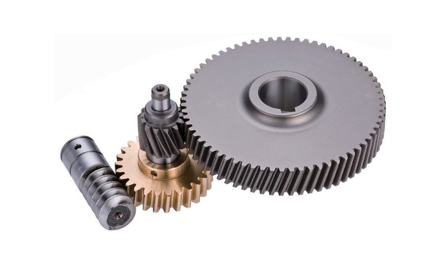
Gear is one of the indispensable parts of mechanical manufacturing. The main function of the wheel is to transmit power. Different gear combinations can play different roles. Acceleration, deceleration, and direction change are all possible. This article mainly talks about the relevant knowledge about gears.
What is a gear?
A gear is a toothed wheel, which transmits the rotational motion of one shaft to another shaft by its meshing effect, and transmits motion or torsion between the two shafts. A gear is a mechanical element with teeth on the rim that can continuously mesh and transmit motion and power. Gears are toothed mechanical parts that can mesh with each other. The application of gears in transmission has appeared very early.
At the end of the 19th century, the principle of the generative gear cutting method and the special machine tools and tools that used this principle to cut gears appeared one after another. With the development of production, the smoothness of gear operation was paid attention to. Gears are used to change the direction of movement, increase or decrease the speed and output torque. Therefore, the gear transmission can easily change the speed, torque and direction of the power supply.
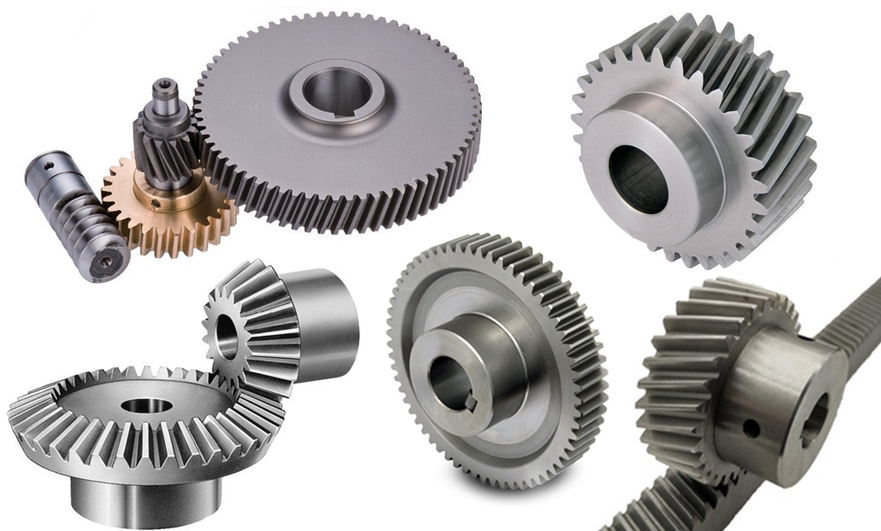
Application and types of gears
There are many types of gears, which are distinguished according to the gear axis.
There are parallel axes: spur gears, helical gears, racks and pinions,
Intersecting axis: Bevel gear,
Non-parallel and non-intersecting axis: worm and worm gear,
According to the position of the shaft, gears can be divided into the following types. There are also categories of herringbone gears, internal gears, helical gears, hypoid gears, and more.
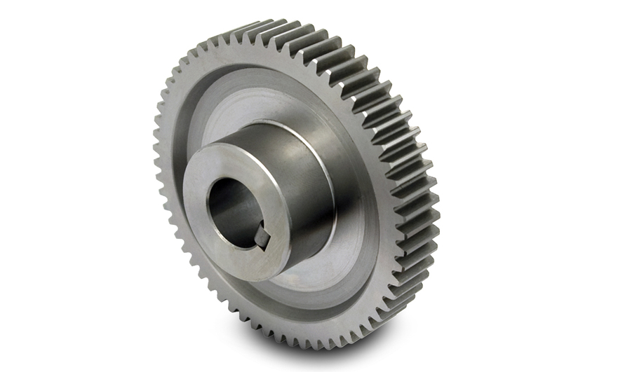
1. Spur gear: The tooth profile contact line is a straight line parallel to the axis. A pair of tooth profiles enter or exit the mesh at the same time along the tooth width, which is easy to cause shock and noise, and the transmission stability is poor. Used to transfer power from one shaft to another parallel shaft, increasing or decreasing the torque of a given object. They are the most widely used gears and can achieve high precision and relatively easy and economical production processes. You can often find them in electric screwdrivers, oscillating nozzles, alarm clocks, washing machines, dryers, construction equipment, fuel pumps, and mills.
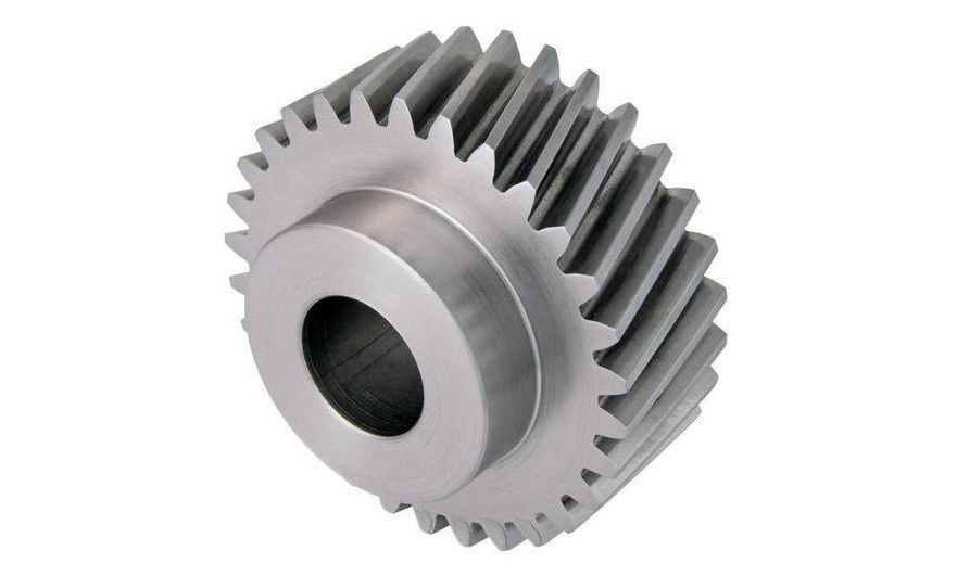
2. Helical gear: The meshing process between the teeth of the helical cylindrical gear is an excessive process, and the force on the teeth gradually increases from small to large, and then from large to small; helical gears are suitable for high-speed and heavy-duty Condition. The increase in the degree of coincidence improves the load-bearing capacity of the gear. Thereby extending the life of the gear. The degree of coincidence mainly depends on the meshing time, and the meshing time of the helical gear is long and the contact area is large, which reduces the stress. And make the transmission stable, and increase its economy. Progressive meshing makes helical gears run more smoothly and quietly than spur gears. Therefore, they have better tooth meshing than spur gears and superior quietness. Helical gears can transmit higher loads, which makes them ideal for high-speed applications.
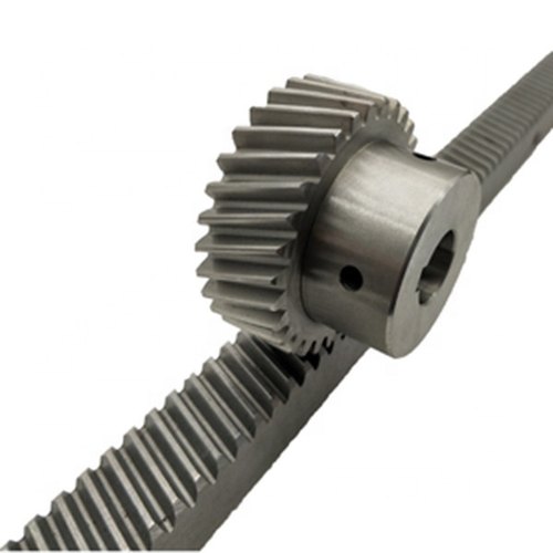
3. Rack and pinion: Rack and pinion is a kind of gear, which includes a circular gear (pinion), which meshes with a linear gear (rack), and its function is to convert rotary motion into linear motion. The rack is a rack or rod. Drive the pinion to rotate to drive the rack linearly, and drive the rack to make the pinion rotate. Rack and pinion provide fewer mechanical advantages than other mechanisms such as recirculating balls. Speaking of the application of this kind of gear, an example is the automobile steering system, which converts the rotation of the steering wheel into the left-to-right movement of the lever.
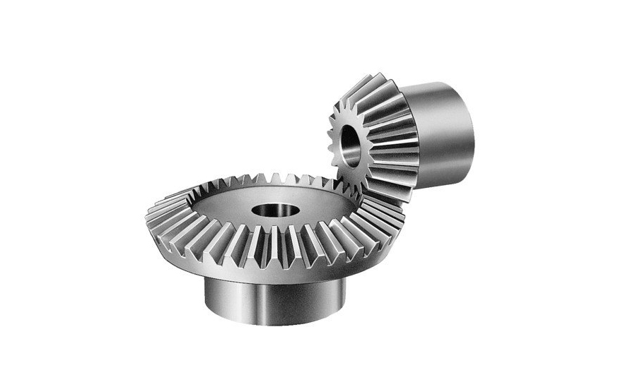
4. Bevel gears: Bevel gears are used to transmit the movement and power between two intersecting shafts. In general machinery, the angle of intersection between the two shafts of bevel gears is equal to 90° (but not equal to 90°). Similar to cylindrical gears, bevel gears have indexing cones, addendum cones, tooth root cones and base cones. The cone has a big end and a small end, and the circle corresponding to the big end is called the index circle (its radius is r), the addendum circle, the root circle and the base circle.
The movement of a pair of bevel gears is equivalent to a pair of pitch cones as pure rolling bevel gears for differential transmission, which can transmit power to the two shafts to rotate at different speeds. It can also be used as the main mechanism of the handle drill. The bit handle rotates in the vertical direction. The bevel gear changes the rotation of the chuck to a horizontal rotation. The bevel gear and hand drill have the additional advantage of increasing the rotation speed of the chuck, making it possible to drill the range of materials.
Bevel gears are widely used, including locomotives, ships, automobiles, printing presses, cooling towers, power plants, steel mills, railway tracks, inspection machinery, etc.
5. Worm and worm gear: The worm gear structure is often used to transmit the movement and power between two interleaved shafts. The worm wheel and the worm are equivalent to the gear and the rack in the middle plane, and the worm and the screw are similar in shape. In the form of a worm meshing with a worm gear, the shape of the worm is similar to that of a spur gear. These two elements are also called worm screws and worm gears. The terms are often confused due to the imprecise use of the terms. The same unit as other gears.
