CNC milling, or computer numerical control milling, is a machining process which employs computerized controls and rotating multi-point cutting tools to progressively remove material from the workpiece and produce a custom-designed part or product. This process is suitable for machining a wide range of materials, such as metal, plastic, glass, and wood, and producing a variety of custom-designed parts and products.
Several capabilities are offered under the umbrella of precision CNC machining services, including mechanical, chemical, electrical, and thermal processes. CNC milling is a mechanical machining process along with drilling, turning, and a variety of other machining processes, meaning that material is removed from the workpiece via mechanical means, such as the actions of the milling machine’s cutting tools.
This article focuses on the CNC milling process, outlining the basics of the process, and the components and tooling of the CNC milling machine. Additionally, this article explores the various milling operations and provides alternatives to the CNC milling process.
Milling Definition
What is milling? It’s is a type of machining that uses cutters to shape a workpiece, often on a moveable tabletop, although some milling machines also feature movable cutters. Milling started out as a manual task performed by humans, but most milling these days is done by a CNC mill, which utilizes a computer to oversee the milling process. CNC milling offers higher precision, accuracy, and production rates, but there are still some situations when manual milling comes in useful. Manual milling, which requires a lot of technical skill and experience, offers shorter turnaround times. It also has the added benefit that manual mills are cheaper and the user doesn’t need to worry about programming the machine.Overview of CNC Milling Process
Like most conventional mechanical CNC machining processes, the CNC milling process utilizes computerized controls to operate and manipulate machine tools which cut and shape stock material. In addition, the process follows the same basic production stages which all CNC machining processes do, including:- Designing a CAD model
- Converting the CAD model into a CNC program
- Setting up the CNC milling machine
- Executing the milling operation
Once the CNC milling process is initiated, the machine begins rotating the cutting tool at speeds reaching up to thousands of RPM. Depending on the type of milling machine employed and the requirements of the milling application, as the tool cuts into the workpiece, the machine will perform one of the following actions to produce the necessary cuts on the workpiece:
- Slowly feed the workpiece into the stationary, rotating tool
- Move the tool across the stationary workpiece
- Move both the tool and workpiece in relation to each other
Generally, milling is best suited as a secondary or finishing process for an already machined workpiece, providing definition to or producing the part’s features, such as holes, slots, and threads. However, the process is also used to shape a stock piece of material from start to finish. In both cases, the milling process gradually removes material to form the desired shape and form of the part. First, the tool cuts small pieces—i.e., chips—off the workpiece to form the approximate shape and form. Then, the workpiece undergoes the milling process at much higher accuracy and with greater precision to finish the part with its exact features and specifications. Typically, a completed part requires several machining passes to achieve the desired precision and tolerances. For more geometrically complex parts, multiple machine setups may be required to complete the fabrication process.
Once the milling operation is completed, and the part is produced to the custom-designed specifications, the milled part passes to the finishing and post-processing stages of production.
CNC Milling Machine Operations
CNC milling is a machining process suitable for producing high accuracy, high tolerance parts in prototype, one-off, and small to medium production runs. While parts are typically produced with tolerances ranging between +/- 0.001 in. to +/- 0.005 in., some milling machines can achieve tolerances of up to and greater than +/- 0.0005 in. The versatility of the milling process allows it to be used in a wide range of industries and for a variety of part features and designs, including slots, chamfers, threads, and pockets. The most common CNC milling operations include:
- Face milling
- Plain milling
- Angular milling
- Form milling
Face Milling
Face milling refers to milling operations in which the cutting tool’s axis of rotation is perpendicular to the surface of the workpiece. The process employs face milling cutters which have teeth both on the periphery and tool face, with the peripheral teeth primarily being used for cutting and the face teeth being used for finishing applications. Generally, face milling is used to create flat surfaces and contours on the finished piece and is capable of producing higher quality finishes than other milling processes. Both vertical and horizontal milling machines support this process.Types of face milling include end milling and side milling, which use end milling cutters and side milling cutters, respectively.
Plain Milling
Plain milling, also known as surface or slab milling, refers to milling operations in which the cutting tool’s axis of rotation is parallel to the surface of the workpiece. The process employs plain milling cutters which have teeth on the periphery that perform the cutting operation. Depending on the specifications of the milling application, such as the depth of the cut and the size of the workpiece, both narrow and wide cutters are used. Narrow cutters allow for deeper cuts, while wider cutters are used for cutting larger surface areas. If a plain milling application requires the removal of a large amount of material from the workpiece, the operator first employs a coarse-toothed cutter, slow cutting speeds, and fast feed rates to produce the custom-designed part’s approximate geometry. Then, the operator introduces a finer toothed cutter, faster cutting speeds, and slower feed rates to produce the details of the finished part.Angular Milling
Angular milling, also known as angle milling, refers to milling operations in which the cutting tool’s axis of rotation is at an angle relative to the surface of the workpiece. The process employs single-angle milling cutters—angled based on the particular design being machined—to produce angular features, such as chamfers, serrations, and grooves. One common application of angular milling is the production of dovetails, which employs 45°, 50°, 55°, or 60° dovetail cutters based on the design of the dovetail.Form Milling
Form milling refers to milling operations involving irregular surfaces, contours, and outlines, such as parts with curved and flat surfaces, or completely curved surfaces. The process employs formed milling cutters or fly cutters specialized for the particular application, such as convex, concave, and corner rounding cutters. Some of the common applications of form milling include producing hemispherical and semi-circular cavities, beads, and contours, as well as intricate designs and complex parts with a single machine setup.Other Milling Machine Operations
Besides the aforementioned operations, milling machines can be used to accomplish other specialized milling and machining operations. Examples of the other types of milling machine operations available include:Straddle milling: Straddle milling refers to milling operations in which the machine tool machines two or more parallel workpiece surfaces with a single cut. This process employs two cutters on the same machine arbor, arranged such that the cutters are at either side of the workpiece and can mill both sides at the same time.
Gang milling: What is gang milling? Gang milling refers to milling operations which employ two or more cutters—typically of varying size, shape, or width—on the same machine arbor. Each cutter can perform the same cutting operation, or a different one, simultaneously, which produces more intricate designs and complex parts in shorter production times.
Profile milling: Profile milling refers to milling operations in which the machine tool creates a cut path along a vertical or angled surface on the workpiece. This process employs profile milling equipment and cutting tools which can be either parallel or perpendicular to the workpiece’s surface.
Gear cutting: Gear cutting is a milling operation which employs involute gear cutters to produce gear teeth. These cutters, a type of formed milling cutters, are available in various shapes and pitch sizes depending on the number of teeth necessary for the particular gear design. A specialized lathe cutter bit can also be employed by this process to produce gear teeth.
Other machining processes: Since milling machines support the use of other machine tools besides milling tools, they can be used for machining processes other than milling, such as drilling, boring, reaming, and tapping.
CNC Milling Equipment and Components
The CNC milling process employs a variety of software applications, machine tools, and milling machinery depending on the milling operation being performed.CNC Mill Support Software
Like most CNC machining processes, the CNC milling process uses CAD software to produce the initial part design and CAM software to generate the CNC program which provides the machining instructions to produce the part. The CNC program is then loaded to the CNC machine of choice to initiate and execute the milling process.CNC Milling Machine Components
Despite the wide range of milling machines available, most machines largely share the same basic components. These shared machine parts include the:- Machine interface
- Column
- Knee
- Saddle
- Worktable
- Spindle
- Arbor
- Ram
- Machine tool
Figure 1 – CNC Milling Machine Configurations and Components
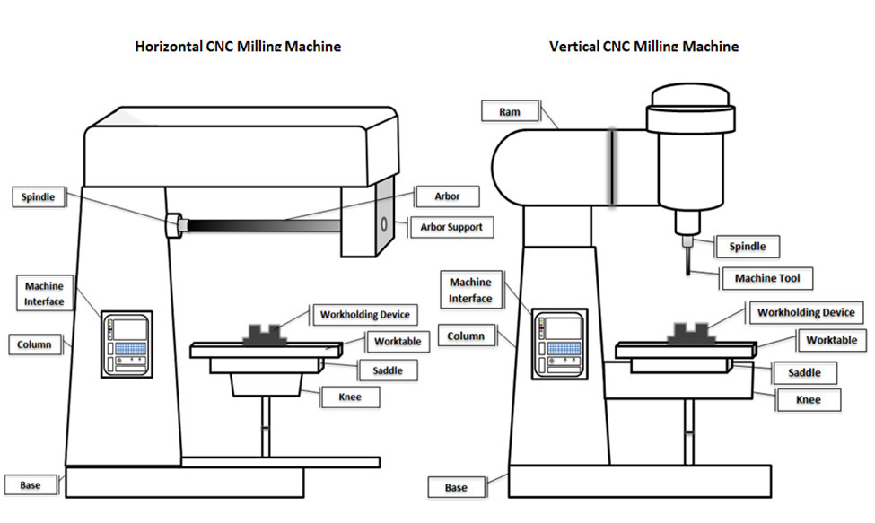
Machine interface: The machine interface refers to the machine component the operator uses to the load, initiate, and execute the CNC machine program.
Column: The column refers to the machine component which provides support and structure to all other machine components. This component includes an affixed base and can include additional internal components which aid the milling process, such as oil and coolant reservoirs.
Knee: The knee refers to the adjustable machine component which is affixed to the column and provides support to the saddle and worktable. This component is adjustable along the Z-axis (i.e., able to be raised or lowered) depending on the specifications of the milling operation.
Saddle: The saddle refers to the machine component located on top of the knee, supporting the worktable. This component is capable of moving parallel to the axis of the spindle, which allows the worktable, and by proxy the workpiece, to be horizontally adjusted.
Worktable: The worktable refers to the machine component located on top of the saddle, which the workpiece or workholding device (e.g., chuck or vise) is fastened. Depending on the type of machine employed, this component is adjustable in the horizontal, vertical, both, or neither direction.
Spindle: The spindle refers to the machine component supported by the column which holds and runs the machine tool (or arbor) employed. Within the column, an electric motor drives the rotation of the spindle.
Arbor: The arbor refers to the shaft component inserted into the spindle in horizontal milling machines in which multiple machine tools can be mounted. These components are available in various lengths and diameters depending on the specifications of the milling application. The types of arbors available include standard milling machine, screw, slitting saw milling cutter, end milling cutter, and shell end milling cutter arbors.
Ram: The ram refers to the machine component, typically in vertical milling machines, located on top of and affixed to the column which supports the spindle. This component is adjustable to accommodate different positions during the milling operation.
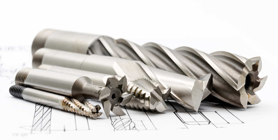
Machine tool: The machine tool represents the machine component held by the spindle which performs the material removal operation. The milling process can employ a wide range of milling machine tools (typically multi-point cutters) depending on the specifications of the milling application—e.g., the material being milled, quality of the surface finish required, machine orientation, etc. Machine tools can vary based on the number, arrangement, and spacing of their teeth, as well as their material, length, diameter, and geometry. Some of the types of horizontal milling machine tools employed include plane, form relieved, staggered tooth, and double angle mills, while vertical milling machine tools employed include flat and ball end, chamfer, face, and twist drill mills. Millings machines can also use drilling, boring, reaming, and tapping tools to perform other machining operations.
Milling Machine Considerations
In general, milling machines are categorized into horizontal and vertical machine configurations, as well as differentiated based on the number of axes of motion.In vertical milling machines, the machine spindle is vertically oriented, while in horizontal milling machines the spindle is horizontally oriented. Horizontal machines also employ arbors for additional support and stability during the milling process, and have support capabilities for multiple cutting tools, such as in gang milling and straddle milling. Controls for both vertical and horizontal milling machine are dependent on the type of machine employed. For example, some machines can raise and lower the spindle and laterally move the worktable, while other machines have stationary spindles and worktables which move both horizontally, vertically, and rotationally. When deciding between vertical and horizontal milling machines, manufacturers and job shops must consider the requirements of the milling application, such as the number of surfaces requiring milling and the size and shape of the part. For example, heavier workpieces are better suited for horizontal milling operations, while die sinking applications are better suited for vertical milling operations. Ancillary equipment that modifies vertical or horizontal machines to support the opposing process is also available.
Most CNC milling machines are available with 3 to 5 axes— typically providing performance along the XYZ axes and, if applicable, around rotational axes. The X-axis and Y-axis designate horizontal movement (side-to-side and forward-and-back, respectively, on a flat plane), while the Z-axis represents vertical movement (up-and-down) and the W-axis represents diagonal movement across a vertical plane. In basic CNC milling machines, horizontal movement is possible in two axes (XY), while newer models allow for the additional axes of motion, such as 3, 4, and 5-axis CNC machines. Table 1, below, outlines some of the characteristics of milling machines categorized by the number of axes of motion.
Table 1 – Characteristics of Milling Machines by Axes of Motion
|
Number of Axes |
Characteristics |
|
3 |
|
|
4 |
|
|
5 |
|
Types of Milling Machines
There are several different types of milling machines available which are suitable for a variety of machining applications. Beyond classification based solely on either machine configuration or the number of axes of motion, milling machines are further classified based on the combination of their specific characteristics. Some of the most common types of milling machines include:- Knee-type
- Ram-type
- Bed-type (or manufacturing-type)
- Planer-type
Ram-type: Ram-type milling machines employ a spindle affixed to a movable housing (i.e., ram) on the column, which allows the machine tool to move along the XY axes. Two of the most common ram-type milling machines include floor-mounted universal horizontal and swivel cutter head milling machines.
Bed-type: Bed-type milling machines employ worktables affixed directly to the machine bed, which prevents the workpiece from moving along both the Y-axis and Z-axis. The workpiece is positioned beneath the cutting tool, which, depending on the machine, is capable of moving along the XYZ axes. Some of the bed-type milling machines available include simplex, duplex, and triplex milling machines. While simplex machines employ one spindle which moves along either the X-axis or Y-axis, duplex machines employ two spindles, and triplex machines employ three spindles (two horizontal and one vertical) for machining along the XY and XYZ axes, respectively.
Planer-type: Planer-type milling machines are similar to bed-type milling machines in that they have worktables fixed along the Y-axis and Z-axis and spindles capable of moving along the XYZ axes. However, planer-type machines can support multiple machine tools (typically up to four) simultaneously, which reduces the lead time for complex parts.
Some of the specialized types of milling machines available include rotary table, drum, and planetary milling machines. Rotary table milling machines have circular worktables which rotate around the vertical axis and employ machine tools positioned at varying heights for roughing and finishing operations. Drum milling machines are similar to rotary table machines, except the worktable is referred to as a “drum” and it rotates around the horizontal axis. In planetary machines, the worktable is stationary, and the workpiece is cylindrical. The rotating machine tool moves across the surface of the workpiece cutting internal and external features, such as threads.
Material Considerations
The CNC milling process is best suited as a secondary machining process to provide finishing features to a custom-designed part, but can also be used to produce custom designs and specialty parts from start to finish. CNC milling technology allows the process to machine parts of a wide range of materials, including:- Metals (including alloy, exotic, heavy duty, etc.)
- Plastics (include thermosets and thermoplastics)
- Elastomers
- Ceramics
- Composites
- Glass
Alternatives
CNC milling is a mechanical machining process suitable for machining a wide range of materials and producing a variety of custom-designed parts. While the process may demonstrate advantages over other machining processes, it may not be appropriate for every manufacturing application, and other processes may prove more suitable and cost-effective.Some of the other more conventional mechanical machining processes available include drilling and turning. Drilling, like milling, typically employs multi-point tools (i.e., drill bits), while turning employs single-point tools. However, while in turning the workpiece can be moved and rotated similar to that of some milling applications, in drilling the workpiece is stationary throughout the drilling operation.
Some of the non-conventional mechanical machining processes (i.e., do not employ machine tools but still employ mechanical material removal processes) include ultrasonic machining, waterjet cutting, and abrasive jet machining. Non-conventional, non-mechanical machining processes—i.e., chemical, electrical, and thermal machining processes—provide additional alternative methods of removing material from a workpiece which do not employ machine tools or mechanical material removal processes, and include chemical milling, electrochemical deburring, laser cutting, and plasma arc cutting. These non-conventional machining methods support the production of more complex, demanding, and specialized parts not typically possible through conventional machining processes.
Summary
Outlined above are the basics of the CNC milling process, various CNC milling operations and their required equipment, and some of the considerations that may be taken into account by manufacturers and machine shops when deciding whether CNC milling is the most optimal solution for their particular machining application.To find more information on domestic commercial and industrial suppliers of custom manufacturing services and equipment, visit the CNCMF.com